Project 03 — Assistive Technology / Mechanical Design

Wiffle
Wafter

Jan 6 — Apr 4, 2026

Subject Matter Expert

CAD · 3D Printing · Fabrication

Under $50

01

Project Overview

The goal of Project 3 was to design a real-world solution for our client Mark — a retired individual living with juvenile arthritis. The condition significantly limits his grip strength, fine motor control, and upper body endurance.

One area directly affected is his ability to play with his dog, Rosie. Mark struggles to throw a ball far enough to engage her in a meaningful game of fetch. Our solution: a mechanical ball launcher that restores that connection.

The design prioritized Mark's limitations at every step — from mechanism selection to handle ergonomics — while targeting commercial viability.

Design Objectives

Light & accessible · Under $50 · Durable · Commercially generalizable · Safe for user & dog
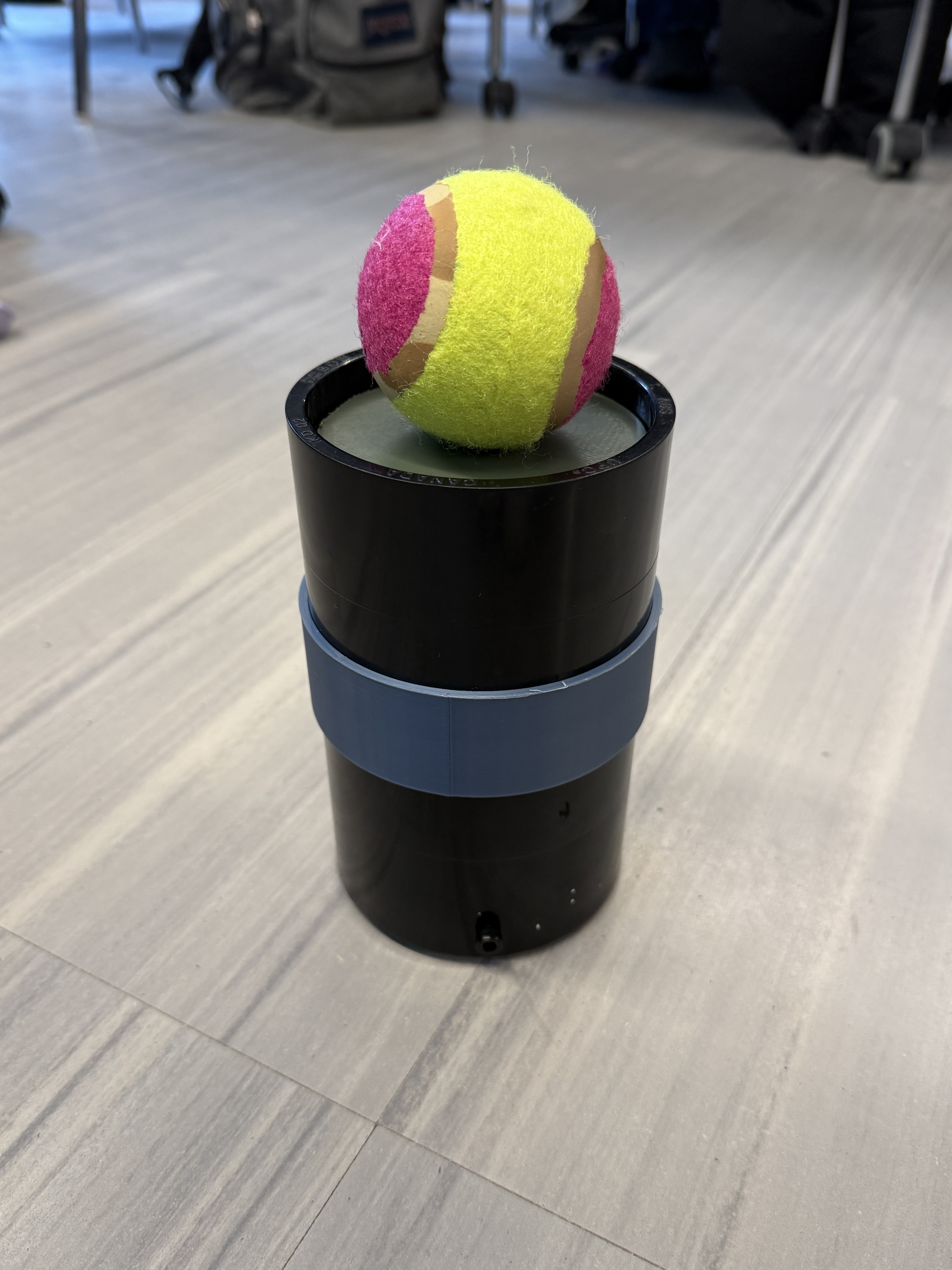
Final Wiffle Wafter prototype
Figure 1 — Final prototype
01
Light & Accessible for Mark to use
02
Low Cost — under $50
03
Durable construction
04
Potential for commercial application
05
Safe for user & dog
06
Launch distance ≥ 7.5 m
02

Individual Contributions

I served as the Subject Matter Expert for this project — maintaining an accurate database of sources and references, and ensuring the project report was completed on time with full team participation.

Beyond my defined role, I contributed across the full design and build pipeline: creating initial concept sketches, refining them into CAD models, fabricating the handle and barrel, and leading the final testing phase with another team member.

Responsibilities

  • Maintained references & source database
  • Ensured report completion and team participation
  • Concept sketching and CAD modeling
  • Fabrication — handle and barrel
  • Led final testing
Subject Matter Expert

As SME, my focus was keeping the team grounded in evidence. Every design decision was cross-referenced against our objectives and constraints — especially accessibility for Mark.

CAD / Fusion 360 3D Printing Fabrication Testing Documentation
03

Design Process

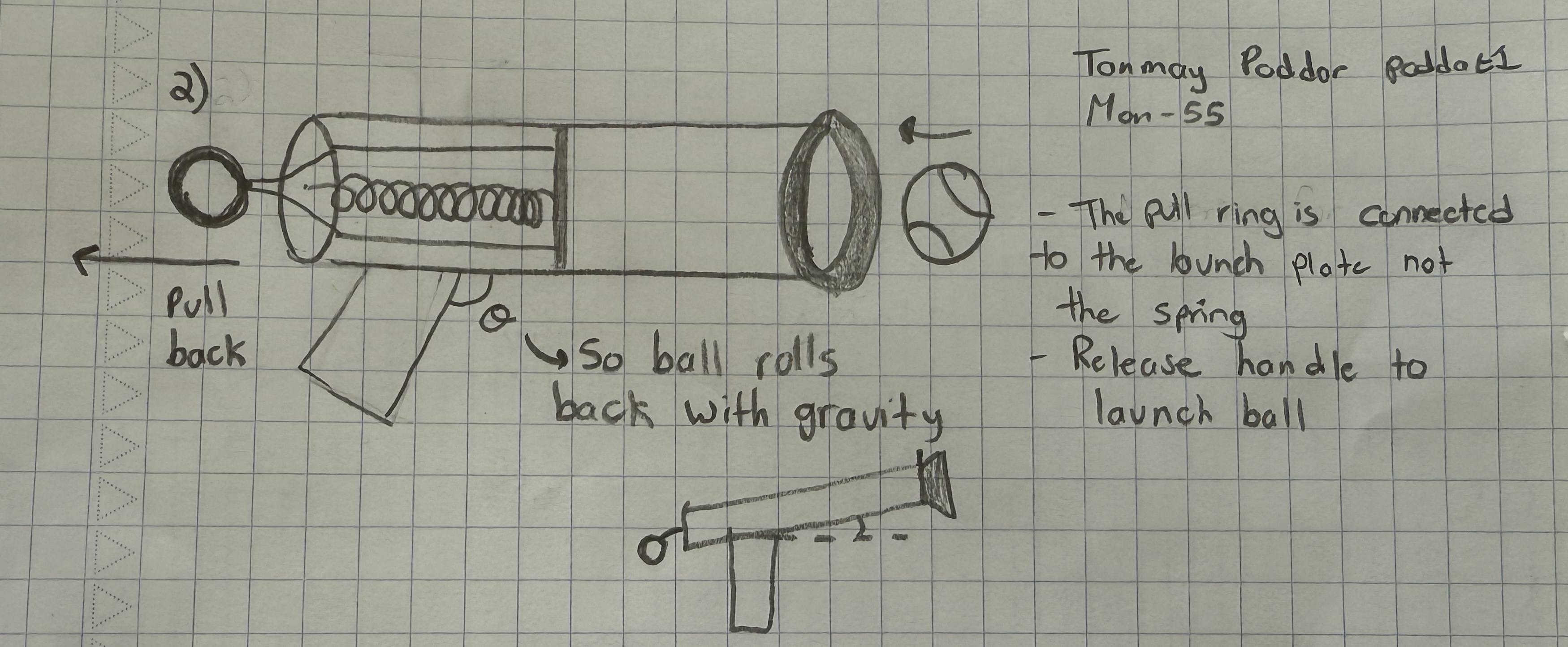
We began by brainstorming mechanisms capable of launching a ball roughly 7.5 m. My first personal concept was a spring-based design where the user pulled back a string handle — minimal moving parts, mountable in a wheelchair cup holder.

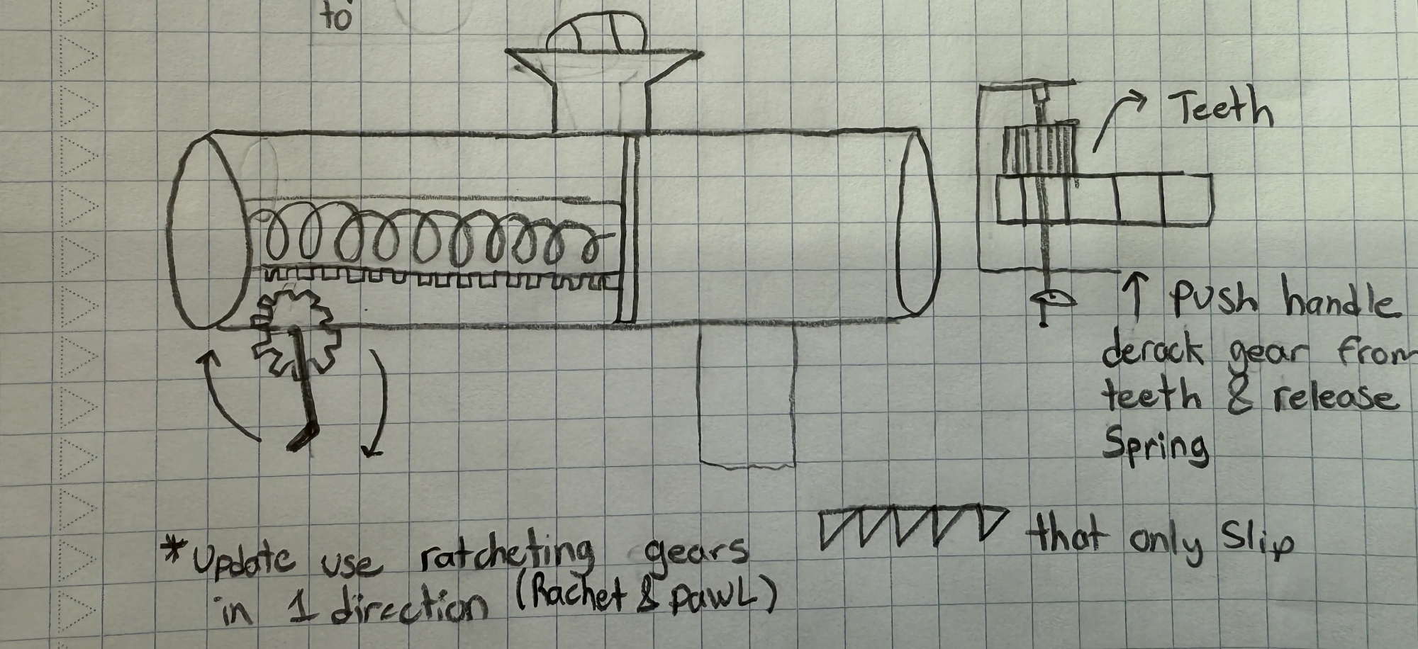
My second concept introduced a rack-and-pinion system with a hand crank to wind a spring, and ratcheting gears to hold tension without requiring constant force from the user. The ratchet-and-pawl mechanism was key — Mark wouldn't need to strain to maintain compression.

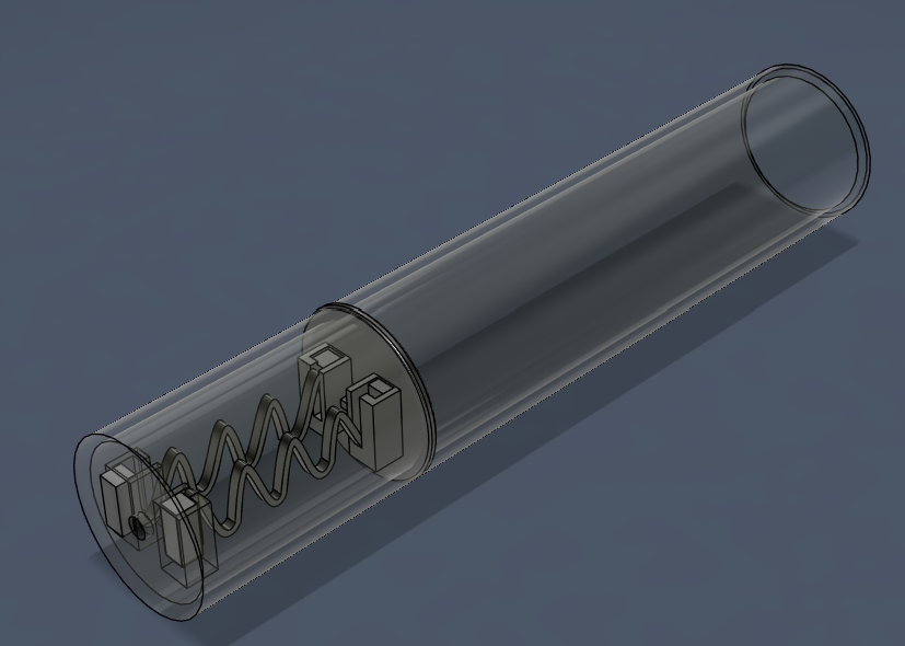
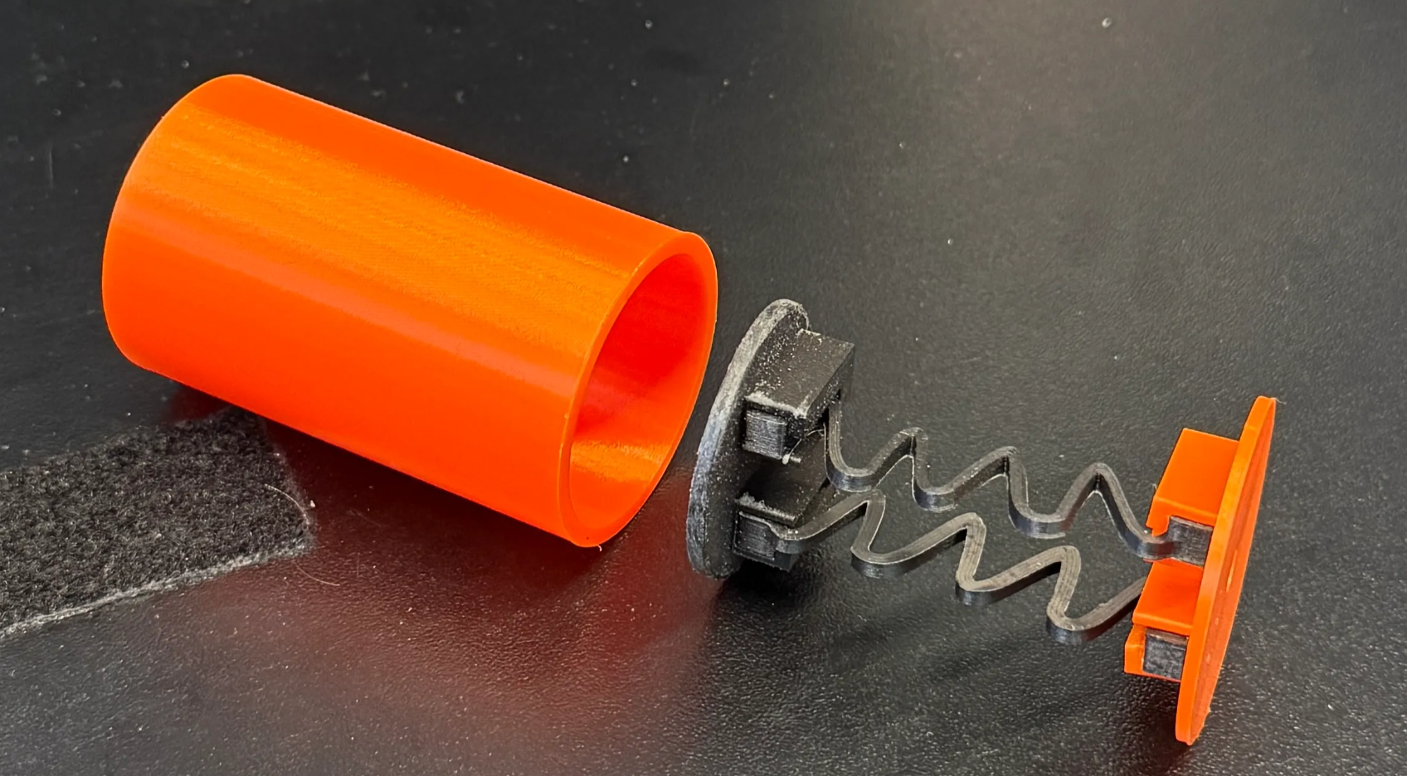
As a team we converged on a pull-back spring mechanism, which I developed into a CAD model featuring 3D-printed springs slotted into attachment points on both ends. A half-scale model was printed to rapidly validate the mechanism before committing to full-scale fabrication.

Spring-based initial concept sketch
Figure 2 — Spring-based concept sketch
Rack and pinion gear-based concept sketch
Figure 3 — Rack & pinion concept sketch
Initial CAD model with 3D printed springs
Figure 4 — Initial CAD model with 3D-printed springs (half-scale)
04

Fabrication & Iteration

After fabricating the half-scale prototype, one of the 3D-printed springs snapped under repeated load. We pivoted to a metal spring, which required rethinking the entire launch method.

3D-printed springs are not ideal for high-stress applications — best reserved for alignment and light-duty uses.

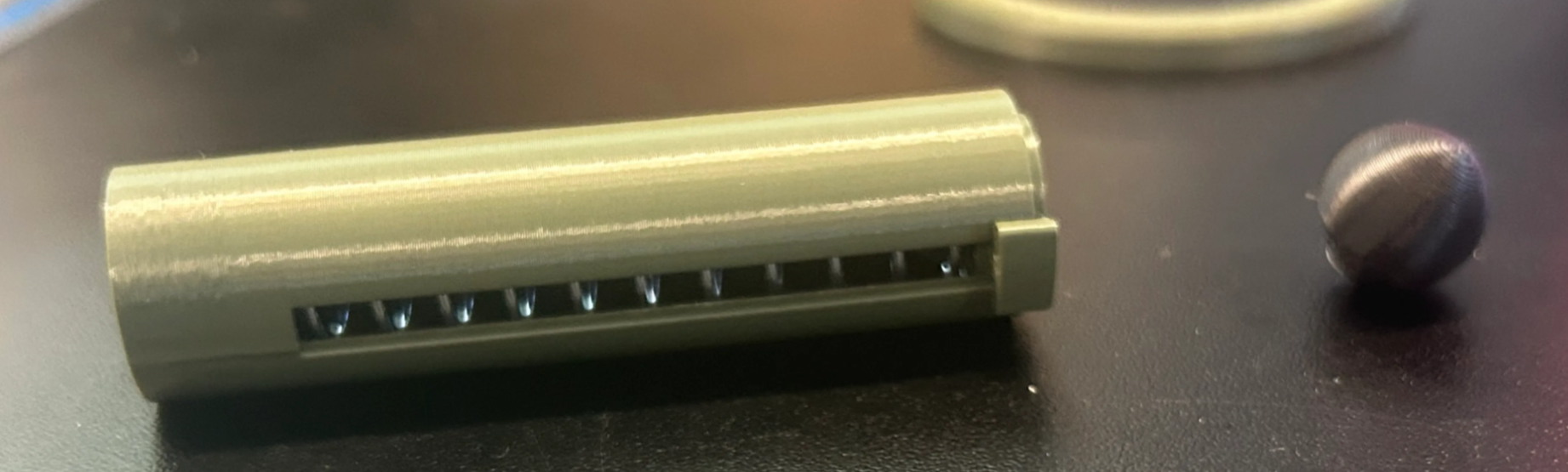
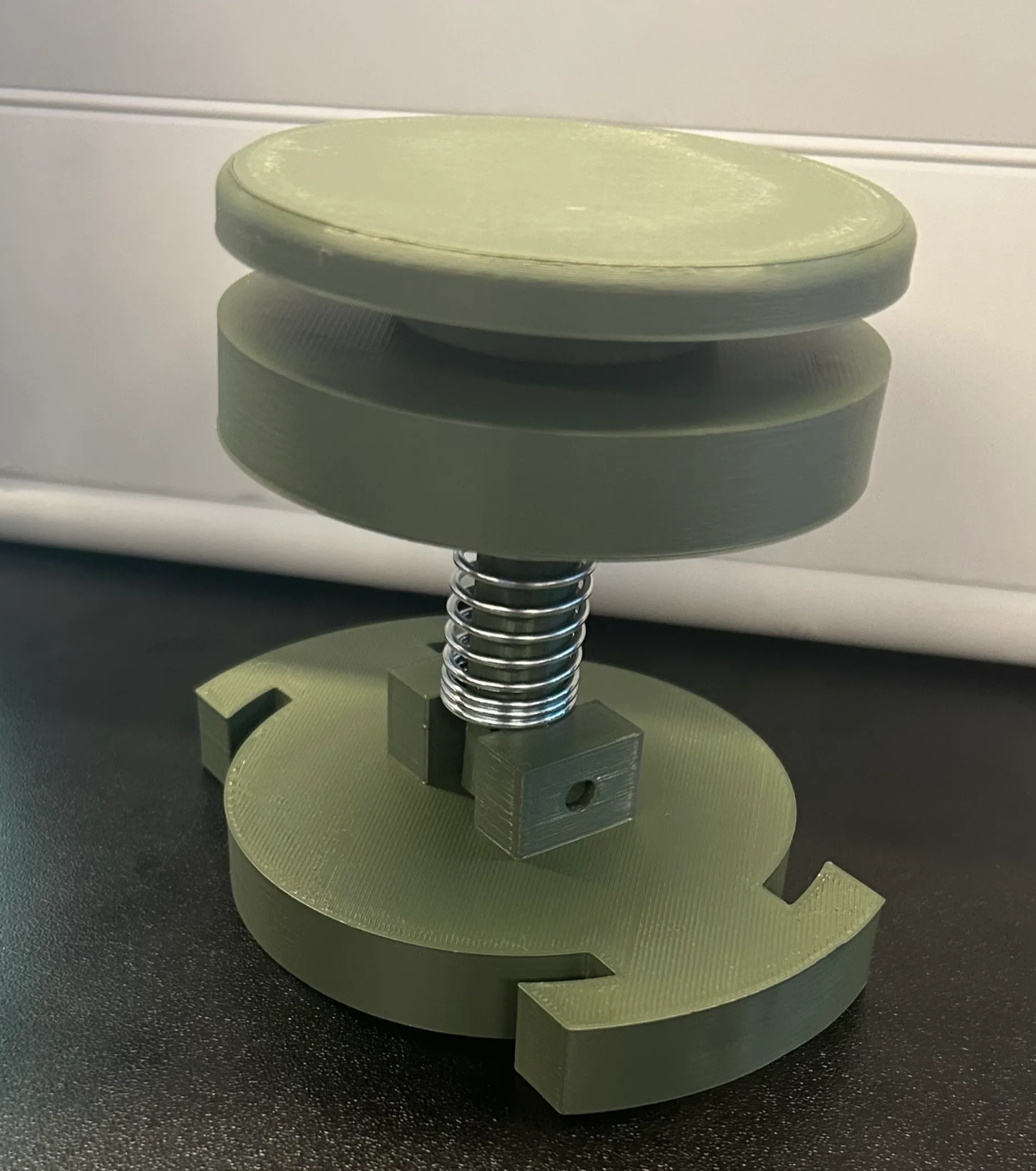
The next iteration used a metal spring with an end plate the user compressed directly. Testing exceeded our target launch distance, but the mechanism jammed repeatedly. We then added a central solid shaft connecting the launch plate through a fixed barrel plate — this resolved the jamming.

The full-scale model revealed a critical insight hidden by small-scale prototyping: applying force off-center (as Mark would from a wheelchair) caused lateral loads on the barrel walls, jamming the launcher. We redesigned for a centrally-pulled handle, reducing off-axis forces and dramatically improving energy efficiency.

Initial half-scale physical prototype
Figure 5 — Half-scale initial prototype
Second prototype with metal spring
Figure 6 — Second prototype, metal spring iteration
Full-scale prototype without barrel
Figure 7 — Full-scale prototype, barrel removed
05

Final Design

The final design uses PVC piping for the barrel and a string handle the user pulls back and releases to launch the ball. The solution proved extremely durable — surviving a drop from the second floor.

Mass and cost came in well below targets, meeting two of our primary objectives with margin to spare.

Strengths

  • Exceptional durability — survived 2nd-floor drop
  • Far below cost and mass targets
  • Comfortable string handle interface
  • Simple, low-maintenance mechanism

Areas for Improvement

  • Spring was underpowered — a stiffer spring would significantly increase launch distance
  • Handle needed greater rigidity for consistent performance

The spring swap is a simple modification. Given one more iteration, launch distance would have comfortably cleared the target.

PVC Barrel Metal Spring String Handle 3D Printing Assistive Design
Final Demo

The final demonstration video (Figure 8) shows the launcher in operation — loaded and fired by a single user with minimal wrist force, validating the core accessibility objective.

Figure 8 — Final demonstration video. If the player above doesn't load, watch it directly on YouTube.
06

Reflection

A core challenge was limited manufacturing time against a design that specified a large prototype requiring long print durations. Our solution: prototype at 1:2 scale. During Week 9 studio, I printed a rough concept, found the spring was mounted at an angle, corrected it, and printed a new model — all in the same session.

We used weighted decision matrices at every crossroads — choosing the ball launcher over a pooper scooper specifically because it offered more universal application, better serving both Mark and Rosie.

Failure is an essential part of the design process. Small prototypes allow faster iteration — but they can be misleading, performing much better than the eventual full-scale model.

Design Philosophy Going Forward

I will integrate rapid prototyping as my default first step: define the objective, build, evaluate, then document what the prototype proved and what it didn't before moving on.

  • Print prototypes at reduced scale when testing mechanism concepts
  • Always test at final scale before committing to a design decision
  • Account for off-axis loading in any mechanism designed for one-handed use
  • Overbuild first — optimize after it works

Iterate quickly and design your prototypes to be simple to fabricate.

← Previous High School Projects Next Project → Robot Arm Effector